Flow Loss Coefficient - Trapezoidal Pipe
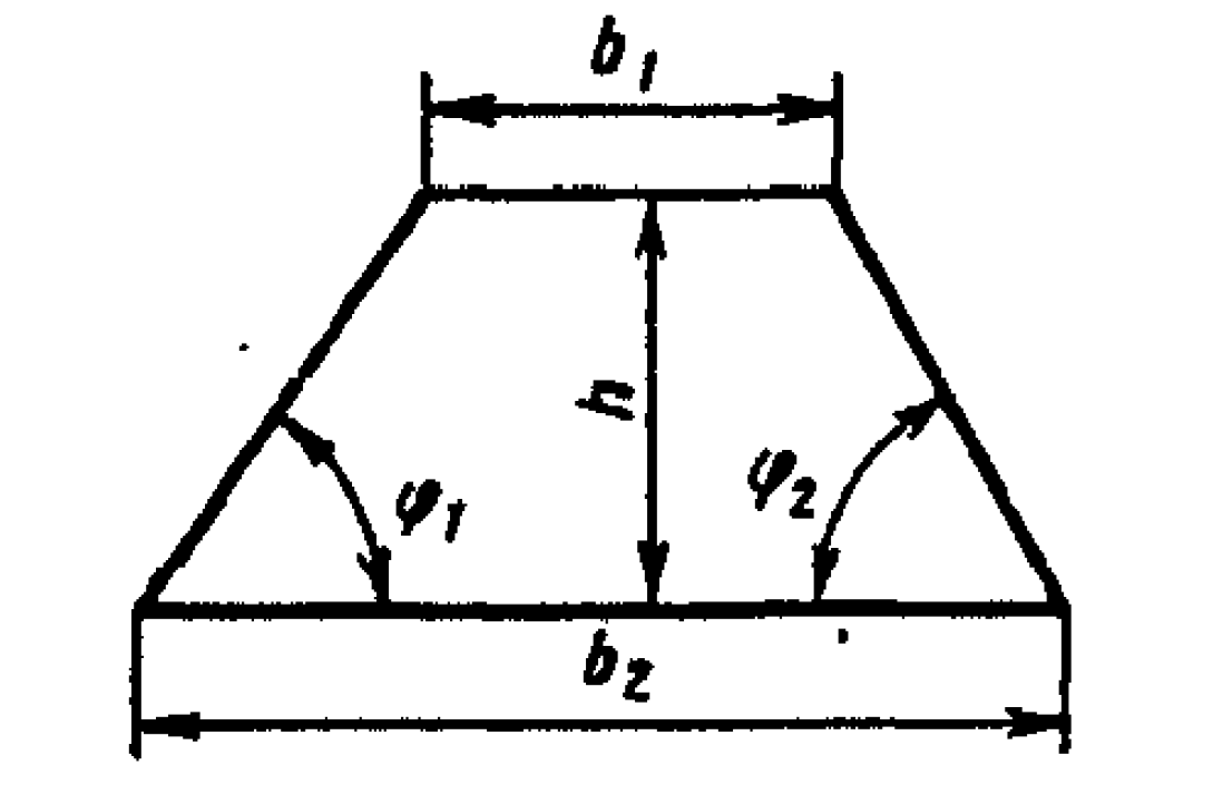
- \( h\) - channel height
- \( b_1\) - channel base width
- \( b_2\) - channel top width
- \( \phi_1\) - left base angle
- \( \phi_2\) - right base angle
Trapezoidal channels are widely used in civil and environmental engineering for stormwater conveyance, canals, and surface water drainage. This page offers pressure loss coefficients (K-factors) tailored to trapezoidal geometries under various flow conditions.
These shapes offer structural stability and reduced excavation volume compared to rectangular channels. Use this page to analyze flow losses and compute the appropriate equivalent hydraulic diameter for accurate head loss calculations.
For pipes of trapezoidal cross section, the flow loss coefficient is defined as:
$$ \lambda = \frac{\Delta p}{(\rho w_0^2 /2)(\ell/D_0)} = k_\mathrm{trap}\lambda_\mathrm{round}$$
where \( \lambda_\mathrm{round}\) is the flow loss coefficient of an equivalent channel of round cross section. See associated calculators for a round channel that is smooth, has uniform sand grain roughness, or has non-uniform roughness.
An equivalent hydraulic diameter for a trapezoidal channel:
$$ \mathrm{D}_H = \frac{4A}{P} = \frac{2h}{1 + \frac{h}{b_1+b_2}\left( \frac{1}{\sin \phi_1} + \frac{1}{\sin \phi_2} \right)} $$
where \( A \) is cross sectional area, and \( P \) is the perimeter
Reynolds number is based on the hydraulic diameter:
$$ \mathrm{Re} = \frac{V \mathrm{D}_H}{\nu}$$
For laminar flow regime (\( \mathrm{Re} \lt 2000 \)):
| \( h/ \left( \frac{b_1+b_2}{2} \right) \) | 0 | 0.1 | 0.2 | 0.4 | 0.6 | 0.8 | 1.0 |
|---|---|---|---|---|---|---|---|
| \( k_\mathrm{rect} \) | 1.50 | 1.34 | 1.20 | 1.02 | 0.94 | 0.90 | 0.89 |
For turbulent flow regime (\( \mathrm{Re} \gt 2000 \)):
| \( h/ \left( \frac{b_1+b_2}{2} \right) \) | 0 | 0.1 | 0.2 | 0.4 | 0.6 | 0.8 | 1.0 |
|---|---|---|---|---|---|---|---|
| \( k_\mathrm{rect} \) | 1.10 | 1.08 | 1.06 | 1.04 | 1.02 | 1.01 | 1.00 |